Viser opslag med etiketten 8bit. Vis alle opslag

onsdag den 15. oktober 2014

New project!

So, the z80 system 2 project being on hold until i get a functioning EPROM burner, I've moved forward on another project: The COSMAC ELF.
Though I've made some hardware mods, it is functionally equivalent of the original ELF. My mods include: 

    - Changing the HEX display to binary LED's; way cheaper.
This mod was actually suggested in the original article.

          - Changed the two 4 bit 2101 RAM's for eight 1 bit 2102 ones.
I had them lying around and besides the "width" they're very similar. Furthermore, they're 1977 vintage - adds something to the design.

    - Sprung for another layout, not wirewrap 
Once again, I'm out of wrap wire, and I kinda wanted it to have more of a Altair 8800 / MIPS 8080 kinda look.

Here it is:

The 8 chips with dual round indents are the RAM.

I have redrawn the schematic into a more reader friendly form than the original, spreading it over 6 pages:
1) CPU and clock
2A) Original RAM
2B) My RAM
3) I/O logic
4) Display
5) Input
6) CPU control

Makes it much easier to debug and alter.

Anyway, so far, I've wired the processor control and power.
Buses are to come.

lørdag den 6. september 2014

Z80 System B update

So, the only thing lacking hardwarewise on the Z80 system I'm building, is the I/O. Once more, I was very inspired by Donn Stewarts z80 project in my port control logic, though I've made a connector for an external "terminal".
As you see, the "terminal" is really just two ports of LEDS as output and slide switches as input. The cable goes to a 40 pin DIL ribbon connector and socket, to port select and latching, etc.

This is the interface board, using the 74LS139 as address decoder/port selector, and 74LS244 for input buffers, 74LS373 for display latches. Still needs wiring.


And Wouldn't you know: The board cracked! when i was scoring the rectangular cutouts for the switches! The pcb material were.. not good; had a consistency as wet crackers, and flaked like slate, meaning when it cracked (the entire bottom right quarter) it sliced  the palm of my hand right up! but i was able to fix it (the board, that is; the hand takes care of itself) by means of screwing on a little piece of pcb on the underside, and solder some of the traces back. Holds quite well. 


fredag den 29. august 2014

The indicator card done

The indicator card made, with a different construction technique, since i wanted to exercise different prototyping methods for digital hardware. Okay, okay; I ran out of wire wrap wire.

Thiss is 26 AWG wire, thicker than W-W. wire, but not much. Still so thin the insulation goes through the standard PCB holes. gives a good deal of strain relief, and allows for use as wire binders.

Not much more to tell about this:


The processor card

The processor card is basically just a z80 with buffered buses and some functions. A clean reset circuit, and two clocks are on board as well. A manual step clock, and a slow clock ( a couple of Hz). This board, the clock and reset in particular, is inspired by CPUville's homebrew z80 project. This also served as the inspiration for this project. 

This is the card. The red % button is the reset, and the toggle switch is the manual clock. the header matrix to the left of the processor is to select the clock via jumper, so you don't accidentally switch on two clocks at the same time. 
Wire color code: RED: When it was closest. BLUE: When that was closest. Power is mainly routed on the solder side.


Computer base and indicator card!

OK, so these come pretty close one after another, since i'm actually past these steps, but behind on making a blog about it.

Well, the base is made, as mentioned from wood, and the Indicator card is made.
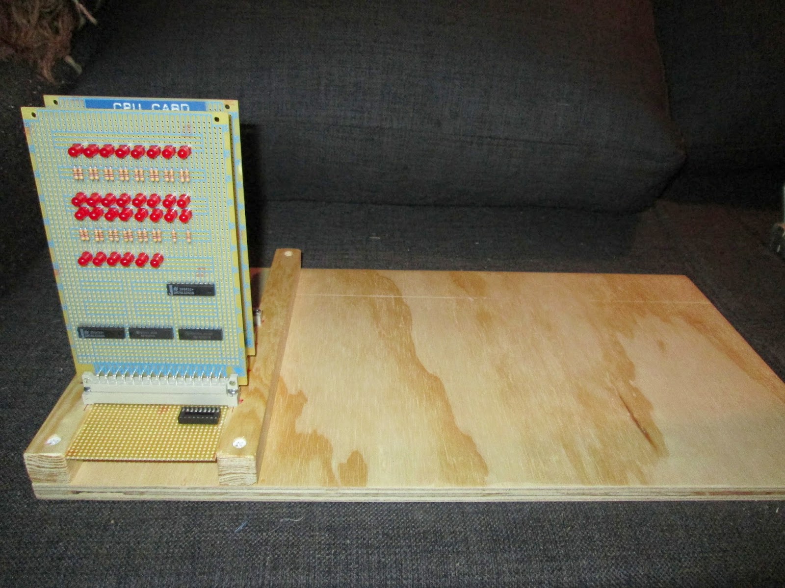
Well this is the indicator /bus display card. It is nothing fancy, just a binary readout of the entire bus. Upper row are DATA (7-0 in reading order), the two rows are ADDRESS(15-0), and the lower six are: Reset, Clock, Memrq, IOrq, RD and WR.
the four chips, 74LS241, is simply set up as noninverting buffers, which has some problems, since most of the control signals are active low. Good thing that won't confuse me when this machine doesn't do a thing!


Here be the base of the computer, the two cards installed. The dip socket on the bus card is to access the data bus, since i got the idea of wanting a little plug with pull-down resistors, to put the processor into free-run mode (just counting addresses, executing NOP's). Room is made for binary I/O, PSU, later: QWERTY keyboard, floppy drive, hard drive. 

Z80 microcomputer (SYSTEM B)

This is the progress on my Z80 computer project! I've recently received the needed components, and has begun construction.

The idea is, to make a eurocard (that's a PCB standard size) and backplane based microcomputer, which can be operated as simply as possible, but that also will allow for infinite expansions. 

Phase 1 consists on little more than a buffered CPU card with clock, and a bus display card, showing the logic level of the address and data bus as well as some control bus signals.

The "enclosure" is made of wood, to give that 70's homebrew feel, and the plan is not to use any component that didn't exist in the early to mid-80's.


Above can be seen the first card to be plugged into the backplane. The connectors are DIN 41617 connectors, because i like how the pins match up with regular stripboard. The card pcb's is IC-island types, FR4 material. The 4 20-pin packages are simply buffers for various busses.

I use a mix of prototyping techniques, here it's wire-wrap, though i use standard 0.1-inch header pins as wrap posts. This has two major advantages, 1) The card becomes very low-profile, with the height being about 1,5 cm instead of the almost 4 with ordinary wrap sockets. 2) each socket costs a fraction of a wire-wrap one. The connection might not be as good, though. I've yet to experience problems with that.